
What are the components of an assembly line? How is the technology implemented?
2026-01-26
Components of an Assembly Line
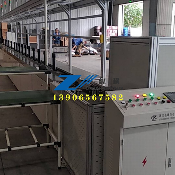
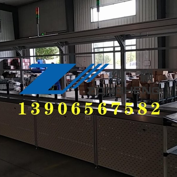
An assembly line generally consists of traction components, load-bearing structures, driving devices, tensioning devices, redirecting devices, and support elements. These components work together to ensure the stable operation and efficient production of the assembly line.
Traction Components: Used to transmit power and drive the load-bearing structures and materials along the assembly line. Common traction components include chains and belts.
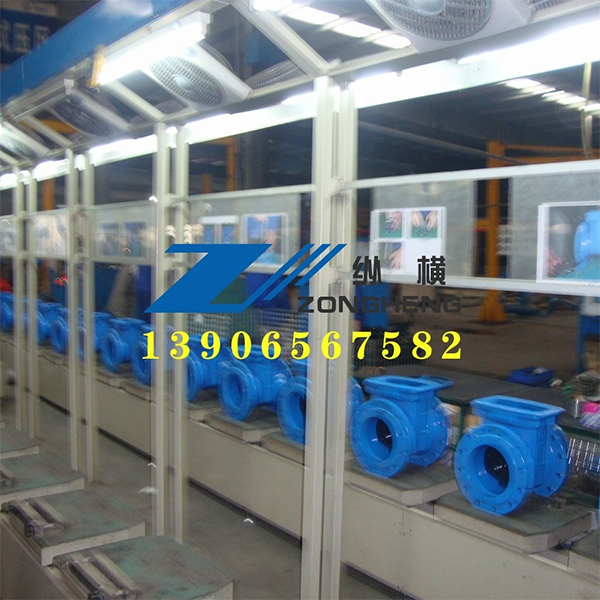
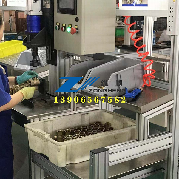
Load-Bearing Structures: Designed to support and carry materials, ensuring their smooth movement along the assembly line. Load-bearing structures come in various forms and can be selected based on the type of material and conveying requirements.
Driving Devices: Provide power to the assembly line, driving the traction and load-bearing components. Driving devices typically consist of motors and reducers.
Tensioning Devices: Used to adjust the tension of the traction components, ensuring they maintain appropriate tension during movement to prevent slipping or loosening.
Redirecting Devices: Alter the direction of movement of the traction components, enabling the assembly line to adapt to different layouts and conveying needs.
Support Elements: Support the various components of the assembly line, ensuring its overall stability and rigidity.
Technical Implementation of an Assembly Line
The technical implementation of an assembly line involves multiple aspects, including hardware structural design and multi-stage coordinated control.
Hardware Structural Design:
Modular Design: The assembly line adopts a modular design, allowing individual components to be independently replaced and upgraded for easy maintenance and expansion.
Standardized Interfaces: Components are connected using standardized interfaces, ensuring compatibility and interchangeability between components.
Optimized Layout: The layout of the assembly line is optimized based on production requirements and site conditions to improve space utilization and production efficiency.
Multi-Stage Coordinated Control:
Instruction Fetch Stage: Predicts the address of the next instruction to prepare for subsequent decoding and execution stages. The address of the next instruction is calculated by the PC incrementer or directly obtained from the constant field by the PC prediction logic unit.
Decoding Stage: Decodes the instruction, reads the values from the registers, and connects the register read ports to the inputs of the arithmetic logic unit (ALU). A single decoding operation can read the values from two registers, providing data support for the subsequent execution stage.
Execution Stage: The ALU performs specified operations based on the instruction function, obtaining the operation result and setting the condition code register. For jump instructions, the execution stage generates a signal based on the condition code and jump condition to determine whether to jump. Simultaneously, the ALU calculates the effective memory access address and performs stack pointer operations.
Memory Access Stage: Writes data to memory or reads data from memory. The data to be written can be provided by the register file or the constant field in the instruction. The memory access stage is a crucial link for data transfer between memory and registers.
Write-Back Stage: Writes the operation result back to the register file. The register file has two write ports connected to the output of the ALU and the output of the data memory, respectively. Based on the currently executed instruction and execution status, it determines whether to write the ALU result or the memory read result back to the register.
News
Hot News
Contact Us
-
Phone:+86-576-86889898
-
Fax:+86-576-86889998
-
Email:2015762548@qq.com